Various Failure Modes in Power Transformers
- The use of fiber optics: Does fiber optic-based monitoring for transformers gain good returns?
- Avoiding thermal stress by implementing cooling system monitoring and controlling
- Optimizing overloading with fiber optics and healthy cooling system
- Benefits of fiber optics based Thermal Monitoring in transformers
Is the most valuable electrical asset of your substation monitored well?
Power transformers are the central part of substations and play a very important role in the power system. They are predominantly unfailing electrical systems. Though they are one of the most reliable components of the electrical grid they are also prone to failure due to many internal and external factors.
As the population of transformers in utility is increasing, much attention must be directed towards transformers reliability and availability. Also, the condition and risk assessment of the transformers are becoming more and more important to improve the transformers performance, extend their useful life, to decrease costs and to take the best technical and economic decisions, concerning their life cycle management.
Different types of transformer failure modes
Failure mode is the way a failure is occurred, observed, which impacts on the equipment operation. The most common failure in transformers is insulation degradation due to overloading conditions, switching surges, lightening etc. The heating of transformer can increase the temperature of insulation system and eventually can decrease the effectiveness of insulation.
The modes of failures can be divided into the following categories:
- Electrical Failure Modes
- Mechanical Failure Modes
- Thermal Failure Modes
Electrical Failure Modes
The Electrically induced factors result in damage to a transformer insulation system. Turn to turn insulation breakdown is the common cause for electrical failure in transformers. Degradation of insulation occurs due to sudden high voltage or current. This breakdown of insulation gives rise to flashover of winding turns and causes short circuits.
Electrical failures can be categorized into the following three main types:
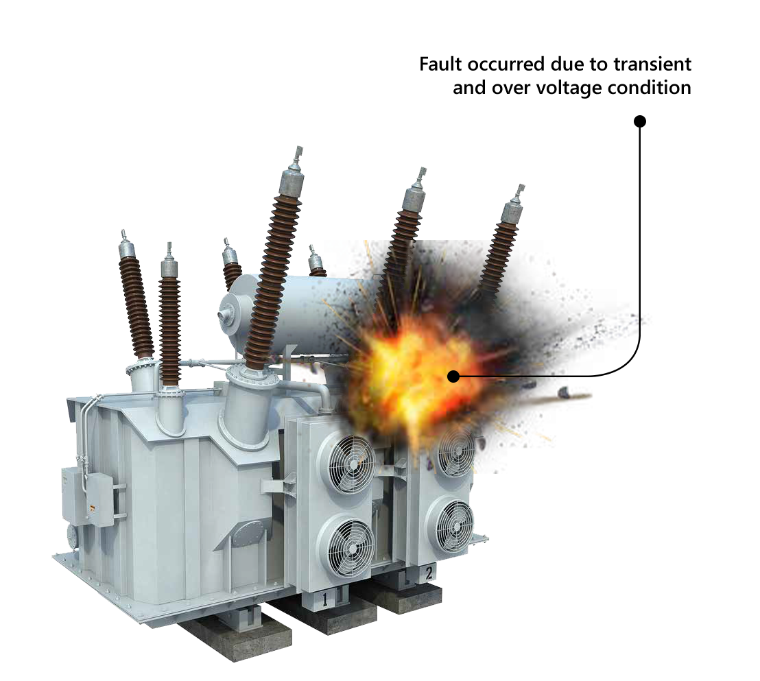
- Transient or overvoltage conditions
- Lightning and switching surges
- Partial discharge
These failures may occur independently or in combination. Therefore, it is important to evaluate all the factors for developing an accurate failure scenario to analyze the failure occurred in the transformer. Transformer insulation should be checked with at most care as the internal electrical failure can result in a catastrophic failure and effect the operations.
Mechanical Failure Modes
Mechanical failures such as distortion or any loose windings result in damage to the transformer windings, i.e., rupturing of its solid insulation. If the damage is acute the transformer can fail electrically. Following are the major mechanical factors responsible for transformer failures:
- Electromagnetic Forces
- Conductor tipping
- Corrosion
- Buckling of the conductor in innermost winding
- Vibration and mechanical movement in transformer
- Failure of coil clamping system
- Displacement of the windings
Thermal Failure Modes
Overloading of the transformer will lead to degradation of cellulose insulation, it deteriorates due to heat, oxidation, acidity, and moisture. This results in the loss of dielectric strength of the insulation in transformer winding. Following are the other factors responsible for increasing thermal stress and loss of insulation in transformers.
- Continuous Overloading of Transformer
- Abnormal loading conditions
- Blockage of oil ducts
- Failure of cooling system
- Environmental conditions
- Overexcitation of transformer
Fault may occur in various parts of the transformer due to the above discussed reasons. The most important parameter to increase the life cycle of transformer would pertain to winding hot spot temperature. Direct temperature measurement of winding hot spots will provide the exact health of the unit. Fiber optic-based temperature monitoring is considered to be the best method compared to other traditional monitoring systems. It has gained huge interest in view of its unique advantages such as immunity to EMI, high sensitivity, fast response, and the potential of monitoring temperature profile inside the transformer.
The current blog articulates about the failure modes caused due to thermal factor and comprehends the monitoring with fiber optics to prevent thermal stress related issues.
The use of fiber optics: Does fiber optic-based monitoring for transformers gain good returns?
The use of fiber optics has mainly been applied to large power transformers with complex design and is recognized as the most accurate method for temperature measurement. Fiber optic temperature sensors are important to maintain reliable power in critical operations. The sensors are highly accurate and provide precise results be it manual or automated measurement. Apparently, they also provide an action plan for condition-based maintenance by providing a clear picture of the actual asset condition, accordingly, to know if there’s any decreased performance before there’s any failure.
Accurate on time winding temperature monitoring
Hot spots are referred to the highest temperature area in the transformer. In transformers hot posts are generally observed in the windings. Condition monitoring of oil temperature and winding inside the transformer ensures its longer life and helps in maintaining the overall health of the asset, as high temperatures in the windings lead to accelerated aging and can signal a breakdown in the insulation or indicate a fault condition. An optimum thermal design will facilitate construction of more efficient and compact transformers by measuring temperature profiles for different designs, including complex-shaped core layouts in distributed and real-time patterns.
Fiber optic temperature sensors can be installed during the manufacturing of transformers enhancing the design features
In addition, the real time monitoring can be implemented at various locations on an energized magnetic core, enabling online monitoring of electrical assets which can identify early evidence of faults. Accordingly, the system will provide alerts to take up any immediate action to avoid catastrophic failure.
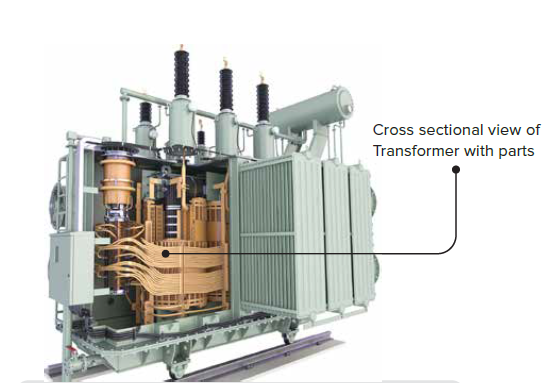
Fiber optic sensors for direct winding hotspot monitoring are designed to sense temperature directly, with the advancement in engineering technology these sensors can be directly installed in high voltage oil filled transformers for measuring oil temperature. The sensors are preferred mostly in recent times, as they are highly immune to harsh environments and any RFI/EMI interference. The following image shows a failure occurred in winding due to hotspots.
![]()
Direct measurement of winding temperature using fiber optic sensors has a clear advantage opposed to values calculated based on uncertain parameters provided by the manufacturer and uncertain equations characterizing the cooling method
Avoiding thermal stress by implementing cooling system monitoring and controlling
Cooling system monitoring and control emphasize on 100% availability of cooling fan banks and pumps to power transformers when required. Copper loss or I2R loss is the main cause of heat generated in an electrical power transformer. Though there are other losses such as hysteresis and eddy current losses which are also accountable for the heat generation, but I2R is considered as the main cause. Thus, if the heat generated is not dissipated properly, the paper or the liquid insulation present in the transformer may get damaged, forcing the transformer to fail permanently. Hence, proper removal or heat treatment is important for efficient working.
The most common method used for cooling is the Forced Air Circulation method. While the temperature inside the transformer goes beyond the standard safe level, an alarm is activated, and the fans and blowers are switched ON automatically or manually. This method is used for transformers with higher ratings.
![]()
With the advanced technology of Fiber Optic Sensors, cooling system can be triggered and monitored, by which we will be able to diagnose the cooling system and receive recommendations, which would not be possible by conventional method.
Optimizing overloading with fiber optics and healthy cooling system
With a continuous change in electricity demand, asset operators face difficulty in predicting sudden changes in load cycle patterns. The change in load cycle patterns occasionally requires loading transformers above their nameplate ratings. Any change in load cycle pattern values can damage transformer windings and insulation. However, overloads are also necessary in emergency or contingency situations and are important to ensure a continuous supply of electric energy.
Overloading of power transformers usually results in conductor temperatures reaching levels above the nameplate rating, which can drastically increase aging of the insulating material. To operate a power transformer in safe condition, permitted heating and loading of the active parts should be limited and to control overload cycles AI based on-line monitoring systems have become important. It is generally recognized that the risks associated with overloading can be significantly reduced if the transformer conditions are closely monitored throughout the overload period.
Compared to traditional sensors, fiber optic sensors determine hot spot temperature by direct measurement rather than making an approximation during the overloading period.
On-line monitoring of winding temperature has become a proven technology to evaluate insulation degradation and the relative loss of life that can be converted into cost. The cost associated with loss of life can be subtracted from the benefits achieved from overloading the transformer. This cost can also be useful while calculating the cost of energy transmitted during overloading conditions.
Benefits of fiber optics based Thermal Monitoring in transformers
Condition based online monitoring of large power transformers has become important due to high economic and social costs associated. In response to this critical requirement, fiber optic sensors are proved to be the preferred method for direct temperature measurement.
There are many technical benefits associated with the use of fiber optics for transformer monitoring
- Safety augment loading and overloading
- Reduces overall physical failure
- Prevents outages and catastrophic failures
- Helps in transformer design and rating verification
Monitoring with fiber optic technology also brings in different commercial benefits such as better knowledge of operational condition assessment, load planning and asset management. End of life determination becomes easier to plan and consequently to manage considering there are less costly interventions.
Following are the prominent commercial benefits associated with the use of fiber optics for transformer monitoring.
- Reduced inspection and maintenance costs
- Reduced failure related or replacement costs
- Improved real-time transformer loading capability
- Reduced capital costs due to manageable overloading
- Reduced replacement capital costs due to equipment age or condition
More to Come in Future
We at Rugged Monitoring offer a wide range of solutions integrated with Fiber Optic Sensors for online monitoring of transformers and other electrical assets.
Keep watching our latest blogs and stories for more updates on failure modes of other segments of transformers with our solutions to them with contemporary technological development.