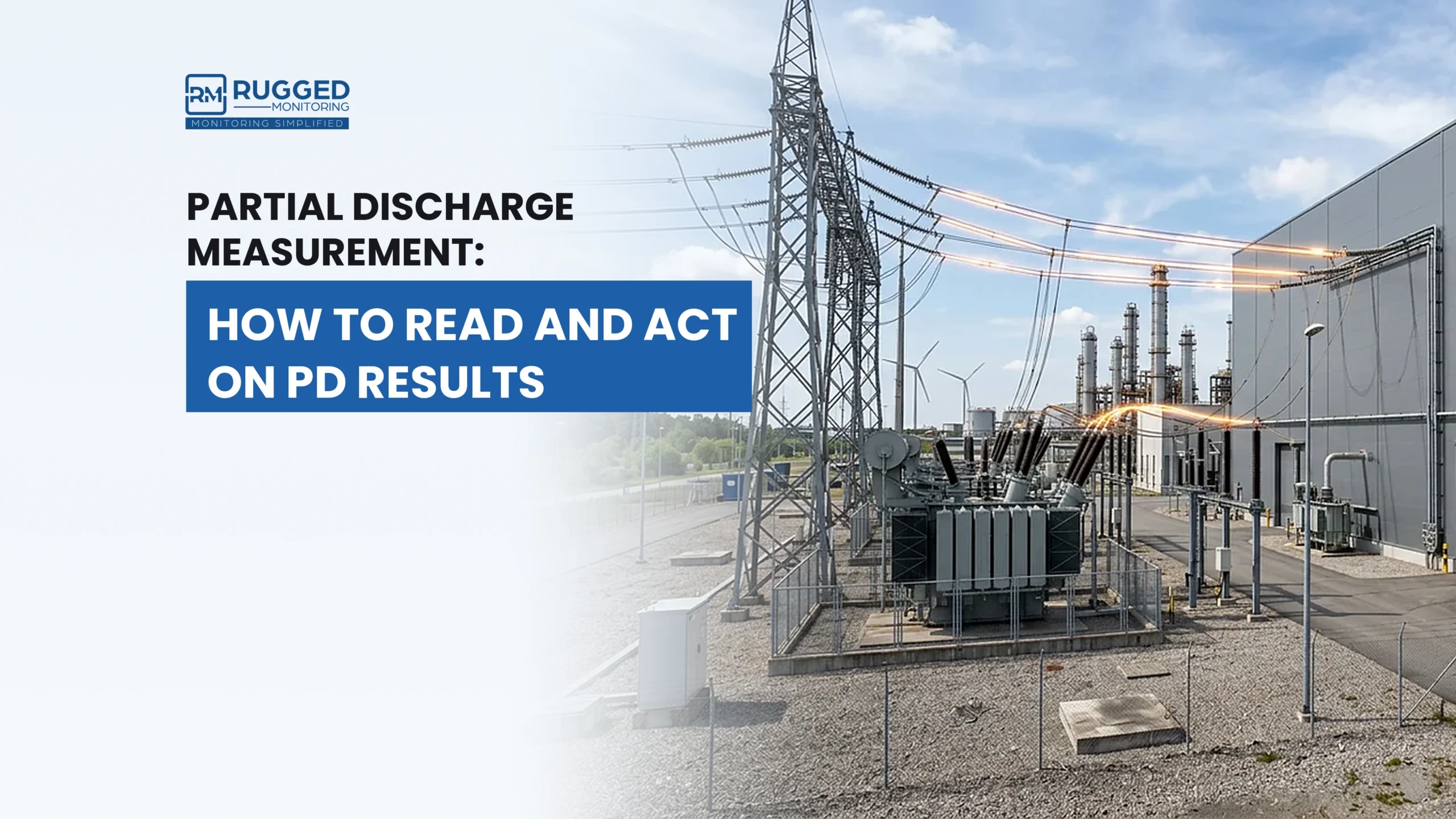

Transformer partial discharge testing measures discharge activity associated with the transformer insulation system to help identify developing insulation defects. Testing can take place during factory testing or in the field, using a measurement arrangement suited to the transformer and test objective.
The measurement itself is only one part of the process. Sensor connections, test conditions, phase reference, measurement channels, and result interpretation all influence what the test can reveal.
So, how is a transformer partial discharge test performed, and what changes when the measurement moves from the factory to the field?
Why does partial discharge testing matter for transformers?
Partial discharge activity can provide information about weaknesses or deterioration within or around a transformer’s insulation system. Measuring and trending this activity can support factory assessment, field diagnostics, and further investigation when insulation condition is in question.
For more background on the phenomenon itself, see Understanding Partial Discharge in Transformers.
Transformer partial discharge test procedure
The exact transformer partial discharge test procedure depends on the transformer design, measurement method, and whether testing takes place in the factory or on site. A typical process includes the following stages.
- Prepare the transformer and test setup
Start by defining the test objective and applicable test condition. Confirm the transformer configuration, available measurement interfaces, required measurement channels, and applicable safety requirements.
The test arrangement should also define how the transformer will be energized or tested and which measurement points will be used.
- Connect the sensors and measurement system
Connect sensors or measurement interfaces appropriate to the transformer and selected partial discharge method. Depending on the transformer and test arrangement, measurement points may include available bushing interfaces or suitable high-frequency current measurement locations.
Sensor type and placement should follow the defined measurement method rather than assuming one sensor arrangement is suitable for every transformer. Different approaches to transformer PD detection are covered in Top Partial Discharge Techniques in Transformers.
- Establish the test voltage and phase reference
The transformer is then placed under the required test or operating condition. The exact voltage arrangement depends on whether the measurement forms part of a factory test, an offline field test, or an online measurement. For a comparison of these approaches, see Online vs Offline Partial Discharge Testing: Choosing the Right Method.
A phase reference allows measured signals to be related to the applied voltage cycle and supports phase-resolved analysis where applicable.
- Acquire the measurements
The measurement system records signals from the selected channels. With synchronized multi-channel acquisition, signals from several measurement points can be captured using a common time and phase reference.
At this stage, measured signals should not automatically be treated as genuine partial discharge. Interpretation considers their pattern, magnitude, phase relationship, measurement location, test conditions, and other available information.
- Record and evaluate the results
Record the measurement configuration and relevant test conditions together with the results. This provides the context needed to compare measurements with a baseline, previous tests, or other measurement points.
Consistent records are particularly important when transformer PD measurements will be repeated over time.
Factory vs on-site partial discharge testing of transformers
Transformer partial discharge measurements may be performed during factory testing or after the transformer reaches the site. The measurement objective and environment differ between the two.
Factory PD measurement is typically performed during the induced-voltage test under IEC 60076-3 (or IEEE C57.12.90 / IEEE C57.113), using the IEC 60270 measurement method. The exact test arrangement depends on the applicable standard, transformer design, and factory test program.
| Factor | Factory testing | On-site testing |
| Purpose | Assess partial discharge activity as part of applicable factory testing and verification | Assess transformer condition after installation or during field diagnostics |
| Test conditions | Planned factory test arrangement | Depends on the installed transformer and field test objective |
| Measurement environment | More controlled test environment | Site environment may introduce additional external signals or constraints |
| Measurement setup | Can be incorporated into the planned factory test | Uses available transformer interfaces and an appropriate field arrangement |
Factory and field results should therefore be interpreted within the conditions under which each measurement was made. A difference between measurements does not automatically indicate a change in transformer condition if the test arrangement or operating conditions have also changed.
Single-channel vs multi-channel partial discharge measurement
A single measurement channel provides information from one measurement point at a time. Multi-channel partial discharge measurement for transformers allows signals from several points to be acquired synchronously.
This adds context because engineers can compare how signals appear across measurement points using the same time and phase reference.
| Factor | Single-channel measurement | Multi-channel measurement |
| Measurement points | One channel at a time | Several channels acquired synchronously |
| Signal comparison | Limited to individual measurements | Signals can be compared across measurement points |
| Phase relationship | Evaluated for the individual channel | Can be compared across synchronized channels |
| Diagnostic context | Provides information from one measurement point | Provides additional context about signal behaviour across the transformer |
Synchronized channels can also support noise discrimination. For example, comparing how a signal appears across several channels can provide additional evidence about whether activity is localized or common to multiple measurement points.
Multi-channel measurement provides additional information that supports interpretation through synchronized comparison of signals from multiple measurement points.
How do you read transformer partial discharge test results?
A transformer partial discharge result should not be interpreted from one value alone. The measurement becomes more useful when it is considered alongside previous results, other channels, and the conditions under which the test was performed.
Three comparisons are particularly useful:
- Compare with the baseline: Determine whether partial discharge activity has changed from a comparable earlier measurement.
- Compare measurement points or phases: Look for differences in signal behaviour across synchronized channels where the measurement arrangement allows it.
- Check the trend: Determine whether the activity remains stable or changes across repeated measurements under comparable conditions.
A change in partial discharge activity does not automatically indicate imminent transformer failure. Its significance depends on the measurement method, pattern, trend, operating context, and other available diagnostic information.
These factors also help determine when changing partial discharge activity requires maintenance attention, rather than treating every increase as an immediate reason for intervention.
How Rugged Monitoring can help
Transformer partial discharge testing becomes more useful when measurements are interpreted in context and compared over time. Depending on the diagnostic objective, the approach may involve periodic testing or ongoing monitoring.
Rugged Monitoring provides partial discharge measurement and monitoring solutions for high-voltage electrical assets, including transformers. Its solutions support periodic field diagnostics as well as continuous transformer partial discharge monitoring, helping asset owners track changing PD activity and investigate developing insulation conditions.
Looking for the right partial discharge approach for your transformer? Contact Rugged Monitoring to discuss your application.
Frequently Asked Questions
How is a partial discharge test of a transformer done?
A transformer PD test uses suitable sensors or measurement interfaces to acquire signals from selected measurement points under defined test or operating conditions. The results are then evaluated using signal patterns, phase relationships, measurement location, and relevant test information.
What is the difference between factory and site PD testing?
Factory PD testing takes place within a planned factory test environment, while site testing uses a measurement arrangement suited to the installed transformer and field objective. Differences in test conditions and measurement setup should be considered when comparing results.
Why use multi-channel PD measurement for transformers?
Synchronized multi-channel measurement allows signals from several measurement points to be acquired using a common time and phase reference. This supports cross-channel comparison and provides additional information for interpreting signal behaviour.
When should transformer PD testing move to continuous monitoring?
Continuous monitoring may be considered when PD activity needs to be tracked over time or when periodic measurements do not provide the required level of condition visibility. The decision should consider transformer condition, criticality, operating context, and monitoring objectives.