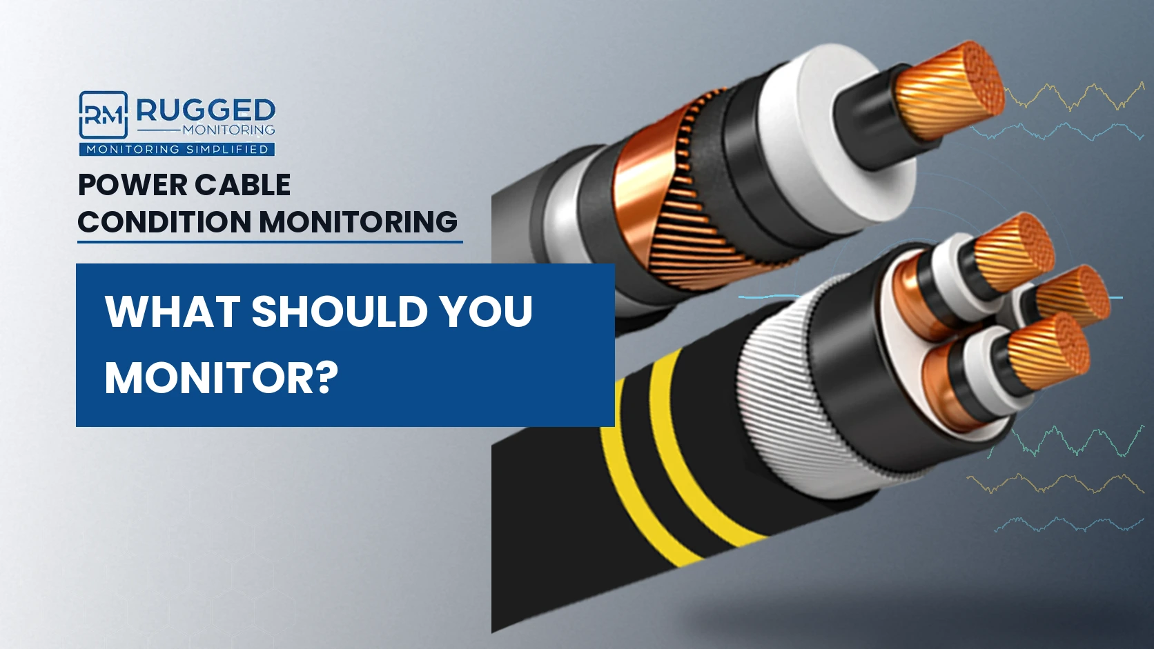
Power cables are fundamental to electrical power systems, carrying power between substations, transformers, switchgear, industrial equipment, and other critical assets. Yet reliable operation does not mean that the cable condition remains unchanged. Electrical, thermal, mechanical, and environmental stresses can gradually affect cable insulation, joints, terminations, metallic sheaths, and other critical components.
The challenge is that much of this deterioration can develop without obvious external signs. A cable may remain in service while partial discharge develops around an insulation defect, a joint experiences abnormal heating, or sheath-current behaviour begins to change. Power cable condition monitoring provides the continuous visibility needed to identify these changes and understand where closer investigation may be required.
This blog examines the complete cable system, not just the cable itself, to explain what should be monitored, where monitoring matters most, which parameters reveal changing cable health, and how condition data can support maintenance and reliability decisions.
Power Cable Health Is a System-Level Problem
A power cable circuit is not one uniform asset. Its reliability depends on several components working together under electrical, thermal, mechanical, and environmental stress.
The cable itself contains the conductor and insulation system together with screens, metallic sheath or shield, protective layers, and other components determined by the cable design. The installed circuit also contains accessories such as joints and terminations, plus grounding and bonding arrangements.
Each part can experience different degradation mechanisms.
The insulation may develop electrical defects. A joint may suffer from installation-related weaknesses, interface problems, or localized heating. A termination may experience thermal or electrical stress. Metallic sheaths and bonding systems can develop abnormal current conditions. External installation conditions can affect heat dissipation and mechanical loading.
This is why cable health assessment should consider the complete circuit rather than treating the cable length as the only component of interest.
However, for maintenance teams, the practical question becomes:
Where can deterioration develop, and which measurable condition will provide evidence of it?
That question provides the foundation for designing a useful monitoring strategy.
Where Should You Monitor a Power Cable System?
Not every point along a cable circuit carries the same failure risk. Monitoring should concentrate on locations where electrical, thermal, mechanical, or installation-related stresses are most likely to create meaningful changes in condition.
-
Cable Joints
Cable Joints create interfaces between cable sections and depend heavily on correct preparation and installation. Electrical-field control, contact quality, and insulation interfaces all influence their long-term performance.
Condition changes around a joint may appear as localized heating or partial discharge activity. This makes joints important locations for both thermal and electrical monitoring.
For example, increasing temperature at one joint relative to comparable joints under similar load may indicate a developing connection or thermal problem that deserves investigation.
-
Cable Terminations
Terminations transition the cable insulation system to other electrical equipment and are exposed to electrical-field stress, environmental conditions, and connection-related heating.
Monitoring termination temperature can reveal abnormal thermal behaviour, while partial discharge monitoring can provide evidence of developing insulation or field-control problems.
-
Cable Length and Route
The cable route itself matters because installation conditions influence thermal performance. Soil characteristics, duct arrangements, grouping, ambient conditions, external heat sources, and other factors can change how effectively heat is dissipated.
Distributed sensing can provide visibility along the route where the application requires broader thermal or mechanical awareness.
-
Sheath and Bonding System
Metallic sheaths, screen connections, bonding leads, link boxes, and grounding arrangements form another important part of the cable system.
Unexpected sheath-current behaviour can provide evidence of abnormal bonding conditions, current imbalance, grounding problems, or other changes requiring investigation.
The right power cable monitoring system therefore begins by mapping failure mechanisms to physical locations, not by deciding how many sensors to install.
Knowing where cable deterioration commonly appears helps determine what should be monitored. The next step is identifying the parameters that provide the clearest insight into cable condition.
What Parameters Should You Monitor for Power Cable Health?
No single condition parameter provides a complete assessment of a power cable system. The strongest monitoring strategy uses parameters that reveal different forms of stress and deterioration.
Four areas are particularly useful: temperature, hotspots, partial discharge, and sheath current. Supporting operating and environmental information can then provide context for interpreting changes.
-
Temperature: Is the Cable Operating Within Its Thermal Environment?
Temperature is one of the most important indicators of cable operating condition because insulation aging and cable loading are closely linked to thermal behaviour.
Cable temperature is influenced by load current, ambient conditions, installation geometry, heat dissipation, neighbouring circuits, and local environmental conditions. Joints and terminations may experience additional localized thermal stress.
Temperature monitoring becomes more useful when engineers evaluate trends rather than isolated values.
For example, a termination that consistently becomes hotter than the other phase under similar conditions deserves attention. This remains true even when its temperature is below the established alarm threshold.
Sustained operation at elevated temperatures can accelerate insulation aging and reduce the expected service life of cable components.
-
Hotspots: Where Is Abnormal Heating Developing?
Overall cable temperature and localized hotspot monitoring answer related but different questions.
A cable circuit may operate within expected thermal limits while a specific joint, termination, connection, or cable section develops abnormal localized heating. That hotspot may indicate poor contact, installation issues, excessive local losses, unfavourable heat dissipation, or another developing condition.
The important diagnostic comparison is often not temperature alone but temperature relative to load, ambient conditions, neighbouring phases, and historical behaviour.
Consider three similar cable terminations carrying comparable current. If two remain thermally consistent while the third develops a progressively larger temperature difference, that deviation provides more useful maintenance information than a single absolute reading.
Continuous hotspot monitoring helps establish whether the anomaly is transient or persistent. Depending on the application, fixed temperature sensors, thermal imaging systems, or distributed fibre optic sensing systems monitor temperature at discrete locations or along extended cable sections.
This distinction is important because thermal monitoring should answer both:
-
- How hot is the cable system operating?
- Is any specific location behaving differently from what its operating conditions would suggest?
-
Partial Discharge: Is the Insulation System Showing Electrical Defects?
Partial discharge provides a different view of cable condition. Instead of measuring thermal behaviour, it detects localized electrical discharge associated with defects or stressed regions within or around an insulation system.
For power cables, relevant sources may occur in cable insulation or accessories such as joints and terminations. Partial discharge monitoring can help identify developing electrical defects before they progress to complete insulation breakdown.
The interpretation requires more than asking whether partial discharge is present.
Maintenance teams need to consider the probable source, discharge characteristics, localization, pattern, trend, operating conditions, and measurement configuration. A single partial discharge magnitude does not universally indicate the remaining life of a cable.
Continuous monitoring adds value by showing whether activity remains stable or changes over time.
For example, repeatable partial discharge localized near a cable joint that begins increasing or changing its behaviour across successive operating periods warrants different attention from an isolated, unconfirmed signal.
When further investigation is required, offline diagnostic tests, including partial-discharge measurements and dielectric-loss assessments, can supplement online monitoring and provide additional insight into insulation condition.
-
Sheath Current: Is the Cable’s Metallic System Behaving as Expected?
Sheath current monitoring provides visibility into the behaviour of metallic sheaths, screens, grounding paths, and bonding arrangements.
Cable configuration, induced voltages, load conditions, bonding arrangements, electromagnetic coupling, and system asymmetry influence sheath currents. Changes from expected behaviour can therefore provide useful evidence that something in the cable or bonding system deserves investigation.
Interpretation should be based on the cable design and expected operating behaviour rather than applying one universal current threshold.
The value is strongest when sheath-current data is considered alongside load and other condition measurements. A current change that follows a known operating change has different significance from an unexplained deviation that persists under comparable conditions.
One Parameter Rarely Tells the Whole Cable-Health Story
However, operators should not use the above-mentioned parameters as four independent alarm systems.
A temperature anomaly tells engineers that thermal behaviour has changed. It does not necessarily establish why. Partial discharge provides evidence of electrical activity but does not by itself describe the cable’s thermal condition. Sheath current reveals behaviour within the metallic and bonding system but requires operating context for interpretation.
Combining these signals can narrow the diagnostic question.
Suppose a cable joint develops increasing partial discharge activity while its temperature remains stable. The evidence points engineers toward an electrical insulation investigation rather than assuming an overheating connection.
Now consider a joint with rising temperature but no corresponding partial discharge trend. The maintenance investigation may focus first on thermal performance, contact condition, loading, or installation factors.
If temperature, partial discharge activity, and another relevant condition indicator all change around the same period, the combined evidence may justify a higher level of attention.
The objective is not to make every parameter confirm every fault. Different measurements are valuable precisely because they observe different aspects of cable behaviour.
This creates a more useful progression:
Condition signal → operating context → correlation → diagnosis → maintenance decision
A strong power cable health monitoring system therefore does more than collect sensor readings. It helps engineers understand relationships between those readings.
How Does a Power Cable Condition Monitoring System Work?
A power cable condition monitoring system works by continuously measuring selected indicators of cable health, collecting and processing the resulting data, and converting that information into actionable maintenance insights. Rather than relying on periodic inspections or isolated measurements, the system tracks how key parameters change over time and highlights deviations that may indicate developing defects.
Most monitoring systems follow a common process:
Measure → Acquire → Analyse → Assess
Sensors Capture the Physical Condition
The monitoring system positions sensors according to the parameter and monitors the failure mechanism.
The monitoring strategy may place temperature sensors at joints, terminations, or other critical points. Fibre optic sensing may provide distributed or multipoint temperature information depending on the system design. Partial discharge sensors capture high-frequency electrical or electromagnetic activity through a method suited to the cable configuration. Current sensors monitor relevant sheath or grounding paths.
The measurement point matters because the sensor must have a reliable physical path to the condition that the monitoring system observes.
Edge Devices Acquire and Process the Signals
Monitoring devices collect sensor signals, perform acquisition and initial processing, and make the measurements available for analysis.
For partial discharge in particular, signal processing and noise discrimination are important because high-voltage environments contain electrical interference that can complicate detection.
Software Creates Trends and Context
Once measurements are stored over time, engineers can move from snapshots to trends.
Historical data allows comparison with previous operating states. Dashboards and alarms can highlight deviations. Correlation with load, ambient conditions, or other parameters can help distinguish normal operational variation from developing abnormalities.
Asset Analytics Support Decisions
The final step is interpretation. Condition information can be combined with maintenance history, asset criticality, known failure modes, and operational consequences to support maintenance prioritization and decision-making.
The value of continuous monitoring therefore comes from the complete chain:
Sensor → data acquisition → trend → condition assessment → maintenance decision
A system that stops at data collection leaves much of that value unrealized. The greatest benefit comes from identifying developing issues before they progress to failure and using that information to support more informed maintenance decisions.
Continuous Monitoring and Periodic Cable Testing Serve Different Purposes
Even the most effective monitoring system cannot answer every condition question on its own. Some investigations require diagnostic techniques that provide a different type of information than continuous monitoring can deliver.
Continuous monitoring observes selected parameters while the cable remains in service, helping engineers identify changes between inspections and understand how conditions evolve over time. Offline testing can answer different diagnostic questions and provide additional information about insulation and cable condition during planned outages or investigations.
The two approaches are complementary. Monitoring can identify developing conditions that justify targeted diagnostic testing, while diagnostic findings may indicate where closer ongoing monitoring is needed.
The strongest cable condition assessment strategy uses each method for the question it is designed to answer.
By combining continuous monitoring with targeted diagnostic testing, maintenance teams gain a more complete understanding of cable condition throughout the asset lifecycle.
This approach can support:
- Earlier investigation of developing abnormalities, allowing teams more time to validate conditions, prepare maintenance activities, and manage outages.
- More condition-based maintenance, helping organizations focus resources on assets showing credible signs of deterioration while avoiding unnecessary intervention on healthy circuits.
- Improved fleet prioritization, where condition information can be considered alongside asset criticality when allocating maintenance resources.
Ultimately, the combination of monitoring and diagnostics provides greater visibility into how cable condition changes over time.
How Should You Design a Power Cable Monitoring Strategy?
A monitoring strategy should begin with the cable system and its risks rather than a list of available sensors.
Start With the Cable Architecture
Document the cable type, voltage class, circuit length, joints, terminations, sheath and bonding arrangement, route, installation environment, and available sensing infrastructure.
This establishes where monitoring is technically practical.
Identify Credible Failure Modes
Determine which problems matter for the specific circuit.
A cable system with critical joints may justify strong thermal and partial discharge coverage. A circuit with complex cross-bonding arrangements may require closer attention to sheath-current behaviour. Installation in thermally constrained routes may increase the importance of temperature visibility.
Map Each Failure Mode to a Measurable Parameter
Do not monitor a parameter simply because a sensor is available.
Ask:
If this failure mechanism begins developing, what measurable condition is likely to change?
Then determine whether that signal can be captured reliably.
Establish Baselines and Trends
Initial measurements provide the reference against which future behaviour can be compared.
This is particularly important because the significance of a change often depends on historical and operating context rather than a generic alarm value.
Define What Happens After an Alarm
A monitoring strategy is incomplete if it ends with a notification.
Teams should know whether an abnormal condition triggers verification, increased monitoring, engineering review, targeted diagnostics, planned maintenance, or escalation.
That turns monitoring into a maintenance process rather than a data-collection exercise.
What Should You Look for in a Power Cable Monitoring System?
Evaluating a monitoring system should begin with a simple question: Can it reliably detect and interpret the conditions that matter most for the cable system being monitored?
Coverage of Relevant Failure Modes
The system should support the parameters needed to identify credible failure mechanisms within the cable circuit. Depending on the application, this may include temperature, hotspots, partial discharge, sheath current, or a combination of measurements that provide a more complete view of cable condition.
Suitable Sensing and Data Quality
Sensors must be appropriate for the cable architecture, installation environment, and measurement objectives. For applications such as partial-discharge monitoring, signal quality and noise discrimination are equally important, as electrical interference can otherwise create misleading results.
Trending and Alarm Management
Monitoring should provide more than real-time measurements. Historical trends, asset-specific alarm settings, and contextual information help maintenance teams distinguish normal operating variation from developing abnormalities.
Integration and Decision Support
Condition data is most useful when it can be incorporated into existing operational and maintenance workflows. Integration with SCADA, historians, or asset-management platforms may be important, but the ultimate objective is interpretation rather than visualization alone. The system should help engineers identify which assets require attention and what actions may be justified.
The right system therefore combines reliable measurements, meaningful trends, and clear condition insight into a practical framework for monitoring cable health.
These capabilities become increasingly important as monitoring is expanded across larger cable networks and critical assets.
Organizations that want to implement these principles at scale require monitoring solutions that bring sensing, analytics, and condition visibility together within a single monitoring architecture.
Building End-to-End Power Cable Condition Visibility
Power cable condition monitoring is most effective when it focuses on the locations and parameters most closely linked to deterioration. Temperature, hotspots, partial discharge, and sheath current each provide different insights into cable health, and together they create a more complete picture of asset condition.
Rugged Monitoring supports this approach with solutions for temperature, hotspot, partial discharge, and sheath-current monitoring. By combining sensing, data acquisition, and condition analytics into a unified platform, these systems help utilities and industrial operators identify developing cable issues before they become operational problems.
Learn more about Rugged Monitoring‘s power cable monitoring solutions and discover how greater condition visibility can support more informed maintenance decisions and long-term cable reliability.